D Cluley
Active Member
POWER WINDOW WIRING 101
Note: This information is correct to the best of my knowledge, based on parts from a 1965 Chrysler. It is possible that other years/models may vary. Please let me know of any errors.
-----------------------
A. Power Feed
This is the circuit breaker for the window system. It is located behind the drivers side kick panel under the dash. The Positive (+) power feeds through the breaker and out in two wires one to the Gang switch on the drivers door, and the other which branches out to the 3 single switches at the other window positions. The ground (-) wire is attached to the body structure with a screw. The large green wire goes to the cigar lighter in the buddy seat or console.
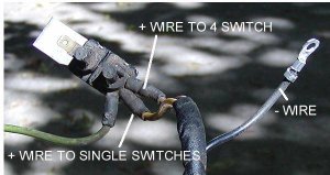
To check this area, make sure there is +12v feeding the output wires, and that the – wire is making a good ground connection.
------------------
B. Gang Switch.
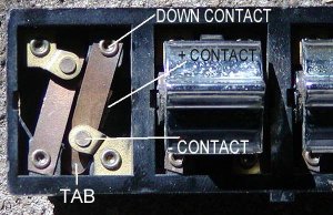
When the window switch is in the neutral position, the down contact is connected to the (-) contact below it. When the button is pushed to the down position the tab is depressed and the down contact is no longer touching the (-) contact. It is now touching the (+) contact which is located underneath. The pair of contacts to the left are for the Up position of the switch, and work the same way.
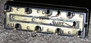
This is the backside of the Gang Switch. The (+) wire feeds the (+) contact on each of the 4 switches, and the (-) wire feeds the pair of (-) contacts on each of the 4 switches.
To test:
With the switches in the neutral positions each of the U pins, and each of the D pins should have continuity with the (-) wire pin. None of the U or D pins should have continuity with the (+) wire pin.
With a switch in the down position, it’s U pin should still have continuity with the (-) wire, but it’s D pin should now have continuity with the (+) wire.
With a switch in the up position it’s U pin has continuity with the (+) wire, and the D pin with the (-)
----------------------
C. Gang switch socket
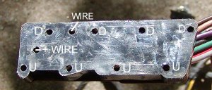
Check to see that the (-) wire is a good ground connection, and that the (+) wire has power
-------------------------
D. Single Switch Socket
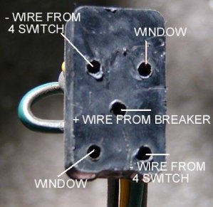
The wires marked Window go to the window motor. Ignore them for now.
The wires marked (-) from 4 switch are connected to the U and D pins on the Gang switch. When the Gang switch for this window is in the neutral position, both of the (-) wires should be a ground connection. If the Gang switch is in the down position, then one of them will be a (+) feed, while the other one remains (-) With the Gang switch in the up position they will be reversed.
The center wire should be a (+)feed all the time. I believe that the (+) feed for each of the single switches are joined together into one wire inside the main harness near the circuit breaker. Therefore if there is no (+) feed, but the (-)feeds are ok, that would be a place to check.
The Single switch sockets are each connected to the main wiring harness with a 3 prong plug set, so if there is no (+) or (-) on any of the wires, checking to make sure that plug is tight should probably be the first thing look at.
-----------------------
E. Single Switch
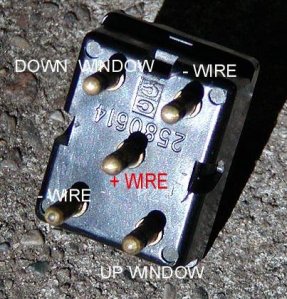
The single switch works basically the same way as the Gang switch, except that the (-) wires are not all connected together. This allows the Gang switch to switch one of them to a (+) feed, and pass it through to the window motor when you move the window from the drivers door. When the single switch is used, it sends the (+) feed from the center post to one wire, and one of the two (-) feeds from the Gang switch, to the other.
To test these switches:
With the switch in the neutral position the Down window pin should be connected to the (-) pin below it, and the Up pin should be connected to the (-) pin above it. There should be no continuity between the Down pin and the (-) pin NEXT to it, or the Up pin and the (-) pin Next to it. There should be no continuity between the (+) pin and any of the other 4 pins.
With the switch in the Down Position, the Down window pin should now be connected to the (+) pin in the center, while the Up window pin is still connected to the (-) above it. The (-) below the Down pin should not have continuity to any of the other pins.
With the switch in the Up Position, the reverse is true. Up pin is connected to the (+) and Down is still connected to the (-) below it.
-------------------
F. Window Motors
The two wires from the single switch socket (and two of the wires coming off of the Gang Switch socket) just go to a connector that plugs into the window motor itself and provide the (+) and (-) power to run the motors, with the polarity switching to go from up to down. The motors themselves do not need to be grounded to the body.
Dan Cluley 2012


Note: This information is correct to the best of my knowledge, based on parts from a 1965 Chrysler. It is possible that other years/models may vary. Please let me know of any errors.
-----------------------
A. Power Feed
This is the circuit breaker for the window system. It is located behind the drivers side kick panel under the dash. The Positive (+) power feeds through the breaker and out in two wires one to the Gang switch on the drivers door, and the other which branches out to the 3 single switches at the other window positions. The ground (-) wire is attached to the body structure with a screw. The large green wire goes to the cigar lighter in the buddy seat or console.

To check this area, make sure there is +12v feeding the output wires, and that the – wire is making a good ground connection.
------------------
B. Gang Switch.
When the window switch is in the neutral position, the down contact is connected to the (-) contact below it. When the button is pushed to the down position the tab is depressed and the down contact is no longer touching the (-) contact. It is now touching the (+) contact which is located underneath. The pair of contacts to the left are for the Up position of the switch, and work the same way.

This is the backside of the Gang Switch. The (+) wire feeds the (+) contact on each of the 4 switches, and the (-) wire feeds the pair of (-) contacts on each of the 4 switches.
To test:
With the switches in the neutral positions each of the U pins, and each of the D pins should have continuity with the (-) wire pin. None of the U or D pins should have continuity with the (+) wire pin.
With a switch in the down position, it’s U pin should still have continuity with the (-) wire, but it’s D pin should now have continuity with the (+) wire.
With a switch in the up position it’s U pin has continuity with the (+) wire, and the D pin with the (-)

----------------------
C. Gang switch socket
Check to see that the (-) wire is a good ground connection, and that the (+) wire has power

-------------------------
D. Single Switch Socket
The wires marked Window go to the window motor. Ignore them for now.
The wires marked (-) from 4 switch are connected to the U and D pins on the Gang switch. When the Gang switch for this window is in the neutral position, both of the (-) wires should be a ground connection. If the Gang switch is in the down position, then one of them will be a (+) feed, while the other one remains (-) With the Gang switch in the up position they will be reversed.
The center wire should be a (+)feed all the time. I believe that the (+) feed for each of the single switches are joined together into one wire inside the main harness near the circuit breaker. Therefore if there is no (+) feed, but the (-)feeds are ok, that would be a place to check.
The Single switch sockets are each connected to the main wiring harness with a 3 prong plug set, so if there is no (+) or (-) on any of the wires, checking to make sure that plug is tight should probably be the first thing look at.

-----------------------
E. Single Switch
The single switch works basically the same way as the Gang switch, except that the (-) wires are not all connected together. This allows the Gang switch to switch one of them to a (+) feed, and pass it through to the window motor when you move the window from the drivers door. When the single switch is used, it sends the (+) feed from the center post to one wire, and one of the two (-) feeds from the Gang switch, to the other.
To test these switches:
With the switch in the neutral position the Down window pin should be connected to the (-) pin below it, and the Up pin should be connected to the (-) pin above it. There should be no continuity between the Down pin and the (-) pin NEXT to it, or the Up pin and the (-) pin Next to it. There should be no continuity between the (+) pin and any of the other 4 pins.
With the switch in the Down Position, the Down window pin should now be connected to the (+) pin in the center, while the Up window pin is still connected to the (-) above it. The (-) below the Down pin should not have continuity to any of the other pins.
With the switch in the Up Position, the reverse is true. Up pin is connected to the (+) and Down is still connected to the (-) below it.

-------------------
F. Window Motors
The two wires from the single switch socket (and two of the wires coming off of the Gang Switch socket) just go to a connector that plugs into the window motor itself and provide the (+) and (-) power to run the motors, with the polarity switching to go from up to down. The motors themselves do not need to be grounded to the body.
Dan Cluley 2012


