wire burned on voltage regulator

Tooltime76

New Member
Joined
Feb 12, 2015
Messages
6
Reaction score
4
Location
Germany
Hello,


I have a Plymouth Fury form 68 and on the voltage regulator for the alternator i saw that a wire burned (see in picture on the left).
Does one know if this is just a regular wire or a resistance wire? If it is a resistance wire what resistance is usually used there?
I tried to measure the leftover (a few inch) with a ohmmeter, but the existing wire is to short to really get a precise value.
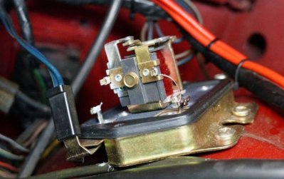
voltage_regulator.jpg


Thank you in advance.


Best Regards
Stefan

voltage_regulator.jpg
 
:sSig_greetingsthor: ............. :welcome:
I'm sure someone smarter then me will jump in with help for you. There's a lot of good knowledge here.

Looks like a nice car from that picture. How about backing up a little and posting some pictures of it.......
 
The only thing that can cause these to burn out like you are mentioning is a constant over load on the electrical system making the alternator to full field all the time so having said that is there any particular time that it burns out such as after you have had the lights or heater on or at night or daytime or both. Does the amp gauge light come on or if you have a meter does it show hi charge rate ? You have a short in the system somewhere. I would first load test your battery to make sure that one of the plates hasn't shorted out.This would cause an overcharge. Also you can check your d.c gauge to see if there is a short there but something is putting a huge draw on the system. You can disconnect the battery cable and put a charger on it and see where the indicator goes on the charger - it is based on amperage and if the needle goes right over then i would suspect that it is your battery causing the problem, if not then check the battery cable itself for corrosion if there are any breaks in it touching bare metal and so on you should check the cable to the starter as well check all the connections at the fire wall and the d/c gauge in the dash and feel wires to see if any are hot. I wouldn't try to repair this regulator, rather replace it with an exact unit after eliminating other issues. To answer your original question, that wire is resistance type capable of changing current flow with temperature through resistance and I'll bet you are "full fielding" the alternator. Above all, if you have an amp gauge do not overlook burnt contacts or poor electrical contact at the bulkhead connector.

 
I wouldn't waste my time on it. I would just simply upgrade to a 70+ regulator. It's an inexpensive up grade.
pic3.gif
 
Thank you very much for the answers.

The previous owner mentioned that he replaced the alternator (defect) just before I bought the car, I guess he did not check the voltage regulator afterwards.
I will exchange the voltage regulator with a electronic one...
Here is a picture of the car....
Seite.JPG

Seite.JPG
 
Welcome to the site from the Motor City!
 
I wouldn't waste my time on it. I would just simply upgrade to a 70+ regulator. It's an inexpensive up grade.
pic3.gif

That will require a 1970 or newer alternator too. The earlier alternators will only have one field (+) connection. The (-) field connection is "internal" and grounds to the alternator case.

The 70 and later alternator is an isolated field with two field (+ and -) connection.

An easy bolt on upgrade for the earlier alternators is an electronic regulator. There's some available that look correct with a case like the mechanical points type... or you can buy a Wells VR-706 electronic regulator from Auto Zone or Advance Auto that looks a little different but still bolts on with no mods to anything.
 
Hello,

thank you, I bought a Regitar C524, that seemed to be the same as the Wells VR-706.
I disconnected the old one and before I connected the new one, I did a continuity measurement (is it called like that in english?) where I measured the FLD (green cable) cable against ground (battery is disconnected) and it seems to be grounded, is that correct?
I also disconnected the FLD cable from the alternator and then the green cable is not grounded, so the cable seems to be not broken.
I am a bit unsure if the alternator is connected correctly...

English is not my mother language, so I hope my wording is understandable :)

Best Regards
Stefan
 
The field connection at the alternator (FLD) will show it is grounded. The pre 70 regulator inputs positive voltage to the field.

Two connections on the alternator. The field (FLD) connection that is a spade connection and the Battery connection that is the screw terminal.
 
The old style Vreg used "high-side switching". It simply outputs full 12 V or nothing to the single alternator "field" terminal. The other field terminal is grounded to the case. The electro-mechanical one in the photo just switches on and off. The newer electronic replacement probably applies a continuously varying voltage from 0 to 12 V, but would still charge the battery fine if it just switched on/off as before (but electronic ignition doesn't like that). You should not measure a short to ground at the "fld" terminal of the Vreg, but rather >10 ohm (kind of guessing). BTW, that "fld" terminal is the screw. The spade terminal is the IGN1 supply.

In contrast, the ~1972+ style Vreg used "low-side switching". Constant 12 V is applied to one alt terminal and the Vreg pulls the other terminal towards ground for more output. That requires running 2 wires to the alternator. They did that because early transistors worked best on the low side. Today it isn't hard to design transistors that regulate on the high side, hence the new replacement like you found.
 
Back
Top